Introduction:
It gives us great pleasure that you have decided to try out this system on
your bike. This kit is something that I spent many years working on it stemmed
from problems I was having with my Bike. Which
is a Yamaha RD350B 1984modell (1974 for you guys). This isn’t a big commercial
product. Nor am I a big manufacturer. Just a simple guy who likes to make things
with his hands.
The kit as you see it now is a far cry from the early kits we shipped
years ago. We pride ourselves on the constant effort to improve the kit. The
separate CDI is the third major revision of our CDI kit. And we are actively
working on the forth and final revision for the same kit. Which will be a
Digital Programmable CDI with a LCD Speedo and RPM counter. You will be able to
upgrade your existing kit to a Digital CDI shortly for a small fee.
Kit Contents:
Base Kit :
Brass
Coil Plate with Lighting / charging, source and pulsar coils
Magnetic
Drum.
Two
New Technology combo HT Ignition Coils with C.D.I OR Separate CDI and HT
coils.
Rectifier
& Regulator
Options:
New
Switch Cluster Left (Turn/PO/Hi-Lo/Horn etc.)
Flasher
(Required for Indicators, requires a batt. to work)
3x1
Instrument Cluster Bulb Holder (high beam/neutral/turn)
Harness
(Complete New Yamaha Harness, everything just plugs in )
Ignition
Switch with Two keys (For R5/RD200/RD250/RD350 etc) Note mounting
clamps may not match. But you have to use our switch. You can switch the
insides with the older switch though.
Clutch
Lever Yoke and Clutch Leaver.
Head
Light Bulb holder (two types).
Indicator
Buzzer (If available).
Fuse
Box for DC Bat.
Installing
the Kit:
The install is
really quite simple. But its best to get it professionally installed.
First
strip bare all the old stuff off your crank end. Like so:
Then
Install the Brass Plate make sure the pulsar is located at the
3.
Then install the drum
over the crank end. Make sure to use the woodruff locating key. Make sure your
key fits in the slot the cam on the drum has. It should be a really tight fit.
Route the blue neutral switch wire from under the brass plate. Also check to
make sure the wires are not pinched between the plate and engine casing.
4.
Now hook up the CDI
harness to the two bullet connectors. Coming off the brass coil plate. On is
source power (Black & Red) the other is pulsar (White blue) this is all
that’s required to make the bike run.
5.
Do not connect up the
Black and white wire on the CDI harness to anything till you have the bike
running. This is the same as the source power in and the only thing it should
hook up to is a kill switch by no means should it touch any DC voltage or join
any other wire as this would fry the CDI. Once you have the bike running the
black&white wire on the CDI harness can be hooked up to the main harness
which has a b&w bullet connector.
6.
The HT Coils have a Green
wire and a Black and Red. Green is earth and black and red is power in. Make
sure the HT Coils are earthed to the frame of the bike by bolting them down
tight scrape off any paint so there is good metal to metal contact, between the
metal part of the HT coils and the body earth.
7.
We repeat do not hook up
anything else except the CDI and HT coils till you get the bike running. Once
its running. You can start installing the other options.
Understanding
the color codes:
Brass
Coil Plate:
·
Black+Red: Source power to HT Coils. (Bullet Female) 280Ohms / 12+ Volts a/c on
kick over. Connects to CDI harness.
·
White
+ Green: Pulsar Signal to
CDI (Bullet Female) 80 Ohms / 2 Volts a/c on kick over. Connects to CDI harness
·
Yellow+Red: Source power Head Light & RR Unit (A/C) 1 Ohms
·
White: Source power A/C to RR for Conversion to DC 1 Ohms
·
Blue: To Neutral switch on White Triangular plastic
·
Black: Earth.
HT
Coils:
Green: Earth must be grounded to chassis
connects to the 2 greens off CDI harness.
Black
& Red: Source power in.
Connects to CDI Harness.
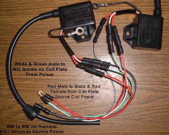
CDI
Box/Harness:
Green White:
Pulsar signal (to Bras coil plate)
Black Red: Source power (to Brass Coil
Plate)
3x Green: Earths one to Body 2 to HT Coils
2x Black Yellow: Source Power to HT
Coils
Black White: Same
as source in only to be connected to Ground to kill engine (Hooks up to a black
and white wire on the Main Harness)
Integrated
CDI: These use 3 Y
Cables that are White, Red, and Black and white. These are used to split the
Source signal from brass plate and pulsar signal to the two HT/CDI units.
Rectifier
& Regulator:
Yellow+White:
A/C power for Head light.
White+Red:
A/C in off coil plate
Red:
DC out 13.5-14.5 Volts. Do not load without a batt. Hooked up.
Black or B&W Earth.
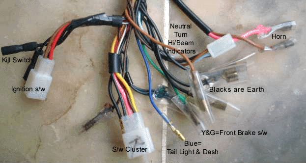
We
have labeled the complete harness. Simply read and plug in required component.
FAQ
Kits
where both CDI systems have been supplied. Which do I use.
We
recommend you use the newer separate CDI system and keep the combo units as a
back up.
Danger
of blowing up CDI.
The
CDI will be damaged if
Note: This by no means cover all the issues that are bound to crop up during your install. If there are any issues not covered here or you just want to discuss how your installation is going please feel free to mail me no matter how small the issue.
If you have one of the newer CDI systems. Please mail me.
The new CDI system is totally different from the CDI covered below. I will be setting up a separate install page for it shortly. The CDI wires are different the Mag drum is different. The coils are different.. And the clearances and mounting screws are different. Check here for New Kit Page. We recommend you read thru this and then move onto the new kit page.
First see that you have received all the parts ordered.
Read this document and the other documents. Develop a plan of action for the install.
Which should be to first install the CDI kit start bike and then move onto installing the harness.
Make sure you remove all the old components from the Crank end. Leaving it bare as shown in picture.
| Remove everything from Crank End. |
 |
It is important to get this step right to ensure the wires are not pinched or pressed up against the engine casing. Which could result in a short or pinch the wires open.
| Route wires exactly as shown |
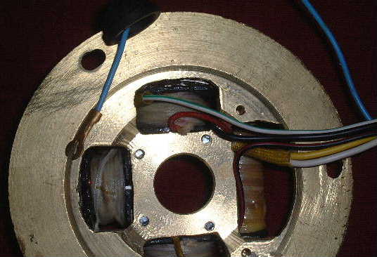 |
| On casing. Note route for Neutral wire and other wires.. |
 |
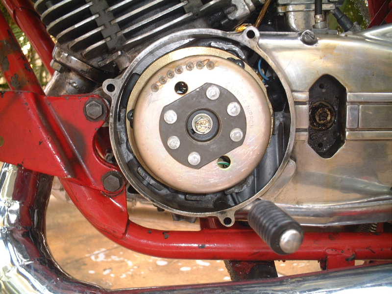
With the plate screwed down shake the harness the wires you see in the picture should move. i.e. make sure they are not pinched between the coil plate and engine casing or crank lip. Now all you need to do is glue the lock key into the crank end and mount up the magnet. If its a high RPM motor. Tighten down bolt to 35 pounds with loclite. Also check this frequently. Likewise for the screws that hold down the Brass Plate.
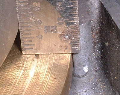
Mag Drum Clearances:
The Kit has been designed with measurement tolerances of 0.5 mm so it is highly unlikely that you should run into any problems. But it is still important that the Drum be installed safely. And getting it to mount with the key is probably the toughest job in the install. Each gap and clearance in the system has a logic and reason behind it. If in doubt please ask a question. (Pictures below taken without the Key.).
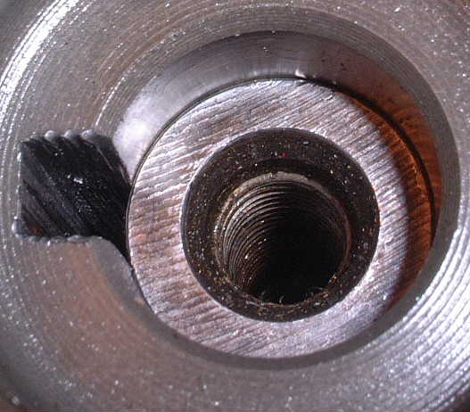
Clearance between the Mag Drum lip and plate should be 6-7mm in the older kits.
In the newer kits that use the more powerful larger cups this clearance is .5mm and the screws are counter sunk to avoid contact.
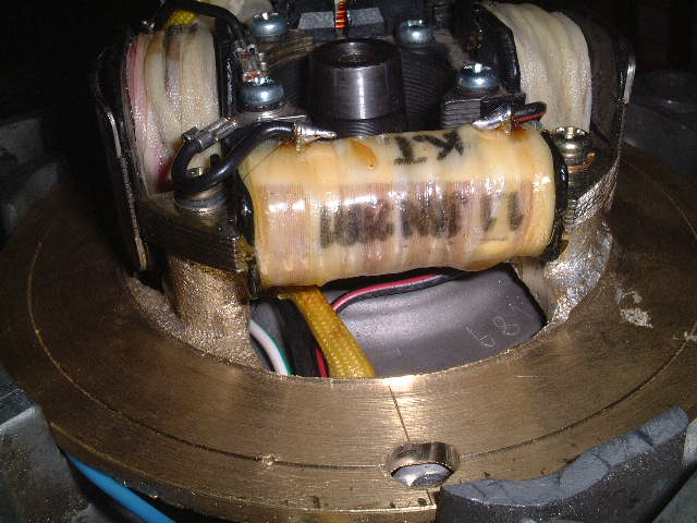
|
Installed on a RD400 |
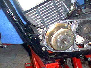 |
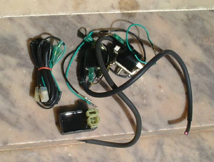
A frequent question is where do I Install the HT Coils. Well we provide a very long lea wire so you can install it where ever you want. People install it in various places from the tool box to the sides of the frame under the tank. I prefer running my coils in the stock position. The little stubs need to be filed off and the coils installed as shown in the picture. Be careful not to make it to tight or the plastic mounting will brake. The coils support each other. The most critical issue is making sure that the Ground makes good contact with the Frame. For this to happen you need to file the paint and any other foreign material on the frame till you see the shinny metal surface. The earth can then be mounted with a nut and bolt. Its also ok to cut the Earth wire and solder on a longer lead if you want to. A sure sign that your earth not making contact is when the bike starts ok but when you rev it past 5000 RPM it starts to backfire.
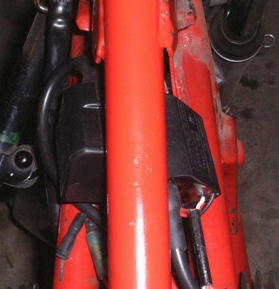
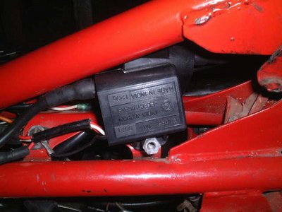
Note: The Units shown in the Picture above are the old CDI/HT coil combo units. If you have the new kit. You do not install these. You install the two separate HT coils. With the Separate CDI unit and the CDI harness. Pictured below
|
Tail Section |
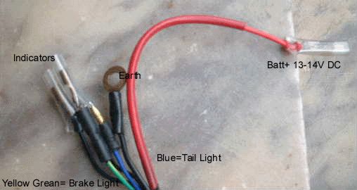 Note: You should use a fuse between Batt+ and Battery. |
|
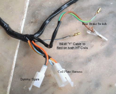
Coil Plate Section |
 |
|
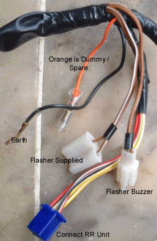
Rectifier Regulator Section |
 |
|
Head Section |
 |
Note:
Before you try to install the harness. We would strongly recommend that you check to see if the bike runs, with the C.D.I kit. This is very simple.
Install only the very basic components of the kit. In this order.
First Coil Plate and Mag. Drum
Then the HT Coils.
Then simply join the Coil plate to the HT coils with the two Y cable provided. One Y caries the pulsar signal telling the C.D.I when to fire and the other carries the power to the HT coils. The third Y cable is the Black&White Cable which hooks up to your harness. Dont connect this one just yet.
Note: The picture above is off the Older CDI Combo Kit. Do not use them even if we sent you a set with your kit. Keep them as an emergency backup. Instead install your Separate CDI box and Coils.
Once the bike is running you can proceed to wire in the rest of the options.
Hope this helps. Mail me if you need any further information.
The reason we keep the Y cables separate from the harness is to allow people who buy the basic kit to get up and running with out any complications.
The reason why we don't have a whole lot of fuses. Is because our system runs on AC. A system that runs its Ignition, Lighting, and everything on DC needs fuses. On our system we do have a fuse between the bat. and the harness. No fuses are required beyond this. Because if there is a short the bike simply wont start.
This is how it looks installed on the bike note first the mag drum then the large nut then the washer then the bolt to hold it all down. Or you can do it any other way just remember to use a washer and make sure the bolt is secured.

Note:
Click on the image above to open it full size (Clearer). Use the full size image if your saving it to your hard disk or printing it.
Note: No matter how sure you are that there is something wrong with the kit. don't panic. The kit has been sold around the world there are tons of people running the kit with no problems what so ever. Yes the first five kits did have some problems which where sorted out. Every now and then when the kit was installed on a new model some issues would crop up which required revisions to the kit. But by the time your reading this the kit has already sold to over 1000 RD owners. So it is highly unlikely that the problem your facing is a Bug in the system. I have noted some of the common problems and questions people run into while installing the kit. This by no means can cover all the possible issues so feel free to mail in your questions. Just don't go "There is something drastically wrong with the kit it cant be installed properly on a RD. Mail in your questions / problems and we will try our best to sort them out.
Lastly please sign up on our BBS and mail us to enable you access to the CDI forum.