It gives us great pleasure that you have decided to try out this system
on your bike. This kit is something that I spent many years working on it
stemmed from problems I was having with my Bike. Which is a Yamaha RD350B 1984modell (1974 for
you guys). This isn’t a big commercial product. Nor am I a big manufacturer.
Just a simple guy who likes to make things with his hands.
The kit as you see it now is a far cry from the early kits we shipped
years ago. We pride ourselves on the constant effort to improve the kit. The
separate CDI is the third major revision of our CDI kit. And we are actively
working on the forth and final revision for the same kit. Which will be a Digital
Programmable CDI with a LCD Speedo and RPM counter. Efforts are being made to
ensure that existing customers can upgrade to this digital CDI for a very reasonable
fee. As soon as its ready.
Contents:
Base Kit :
Brass
Coil Plate with Lighting / charging, source and pulsar coils
Magnetic
Drum.
Two New
Technology combo HT Ignition Coils with C.D.I OR Separate CDI and HT coils.
Rectifier
& Regulator
Options:
1. New Switch Cluster Left (Turn/PO/Hi-Lo/Horn
etc.)
2. Flasher (Required for Indicators, requires a
batt. to work)
3. 3x1 Instrument Cluster Bulb
Holder (high beam/neutral/turn)
4. Harness (Complete New Yamaha Harness,
everything just plugs in )
5. Ignition Switch with Two keys (For
R5/RD200/RD250/RD350 etc) Note mounting clamps may not match. But you
have to use our switch. You can switch the insides with the older switch
though.
6. Clutch Lever Yoke and Clutch Leaver.
7. Head Light Bulb holder (two types).
8. Indicator Buzzer (If available).
9. Fuse
Box for DC Bat.
Installing the Kit:
The install is
really quite simple. But its best to get it professionally installed.
1. First strip bare all the old stuff off your
crank end. Like so:

2. Then Install the Brass Plate make sure the
pulsar is located at the
Also make sure to route the wires behind the plate so that they do not get crimped or crushed between the brass plate and engine. Like so


3. Then install the drum over the crank end.
Make sure to use the woodruff locating key. Make sure your key fits in the slot
the cam on the drum has. It should be a really tight fit. Route the blue
neutral switch wire from under the brass plate. Also check to make sure the
wires are not pinched between the plate and engine casing.

4. Now hook up the CDI harness to the two
bullet connectors. Coming off the brass coil plate. On is source power (Black
& Red) the other is pulsar (White blue) this is all that’s required to make
the bike run.
5. Do not connect up the Black and white wire
on the CDI harness to anything till you have the bike running. This is the same
as the source power in and the only thing it should hook up to is a kill switch
by no means should it touch any DC voltage or join any other wire as this would
fry the CDI. Once you have the bike running the black&white wire on the CDI
harness can be hooked up to the main harness which has a b&w bullet
connector.
6. The HT Coils have a Green wire and a Black
and Red. Green is earth and black and red is power in. Make sure the HT Coils
are earthed to the frame of the bike by bolting them down tight scrape off any
paint so there is good metal to metal contact, between the metal part of the HT
coils and the body earth.
7. We repeat do not hook up anything else
except the CDI and HT coils till you get the bike running. Once its running.
You can start installing the other options.
Understanding the color codes:
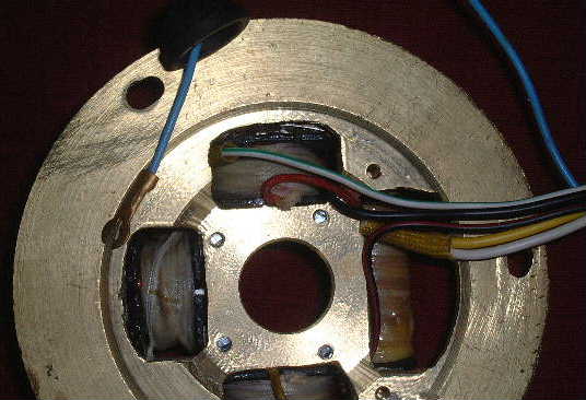
Brass Coil Plate:
·
Black+Red: Source power to HT Coils. (Bullet Female) 280Ohms / 12+ Volts a/c on
kick over. Connects to CDI harness.
·
White + Green: Pulsar Signal to CDI (Bullet Female) 80
Ohms / 2 Volts a/c on kick over. Connects to CDI harness
·
Yellow+Red: Source power Head Light & RR Unit (A/C) 1 Ohms
·
White: Source power A/C to RR for Conversion to DC 1 Ohms
·
Blue: To Neutral switch on White Triangular plastic
·
Black:
Earth.
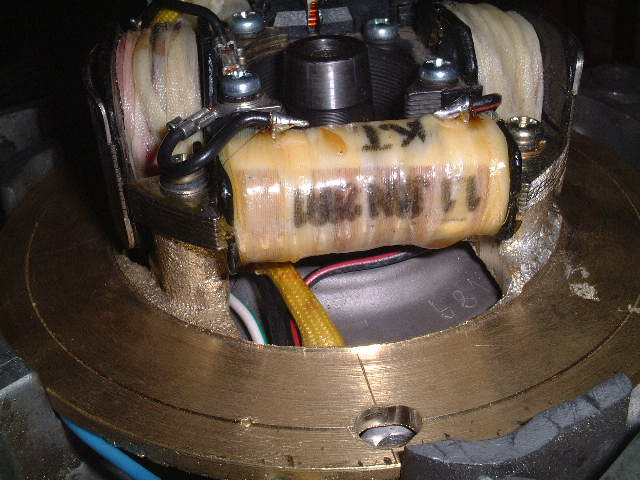
HT Coils:
Green: Earth must be grounded to chassis
connects to the 2 greens off CDI harness.
Black
& Red: Source power in.
Connects to CDI Harness.
CDI Harness:
Green White: Pulsar
signal (to Bras coil plate)
Black Red: Source power (to Brass Coil Plate)
3x Green: Earths one to Body 2 to HT Coils
2x Black Yellow: Source Power to HT
Coils
Black White: Same as source in only to be connected to
Ground to kill engine (Hooks up to a black and white wire on the Main Harness)
Integrated
CDI: These use 3 Y
Cables that are White, Red, and Black and white. These are used to split the
Source signal from brass plate and pulsar signal to the two HT/CDI units.
Rectifier
& Regulator:
Yellow+White: A/C
power for Head light.
White+Red: A/C in off coil plate
Red: DC
out 13.5-14.5 Volts. Do not load without a batt. Hooked up.
Black or B&W Earth.
We have labeled the complete harness. Simply
read and plug in required component.
FAQ
Kits where both CDI systems have been
supplied. Which do I use.
We recommend you use the newer separate CDI system and keep the combo units as a back up.
If you can get your hands on a Single HT coil with dual leads off a bike that came with a CDI like the RZ350 then this HT coil will give you the best performance.
Danger of blowing up CDI.
The CDI will be damaged if
HT Coils used with a CDI are totally different from HT coils that are designed to work with a Battery based system. Using performance coils designed to work with the Bat i.e. DC voltage will damage the CDI.
Please do this at least once. Click here for timing document.